
Hi Steven,
I had started to write up a reply to your question earlier (draft
attached below). But now I'm glad I hadn't sent it yet because your
test results were very interesting to see. Thanks for posting them!
If I understand correctly what you're trying to do, I worry a bit that
you're using a data cable to tie the grounds of different units
together. The reality is that the "grounds" in each unit aren't always
at exactly at the same potential, even though they are supposed to be.
The "grounds" of each unit bounce around a bit. Among other things,
that can sometimes cause current flow in the ground, and EMI, and also
make the data signal appear to have noise on it relative to the ground.
So your "reference point ground" for the digital signal might be
bouncing around and you lose noise margin. It seems like this approach
might work under certain conditions where the grounds are sufficiently
closely tied together and outside noise conditions are low, but then not
work under other conditions (or possibly cause EMI problems).
Probably the further apart the units get the lower the noise margin and
reliability of this single ended link would be.
---
Chuck Corley
My earlier unsent draft:
I know that the nominal impedance of the twisted pairs in Cat5e/Cat6a/Cat7
Ethernet patch cables is 100 Ohms ± some tolerance: ... But is the
single-ended impedance of a pair specified or defined with respect to GND, if
I run a single-ended signal (e.g. TTL) over one leg of a pair and then tie
the other leg of the pair to GND on both sides of the cable?
Ladies & Gents,
TL;DR: It's pretty close to 50 Ohms.
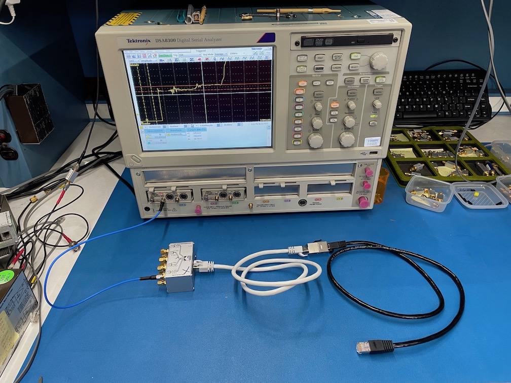
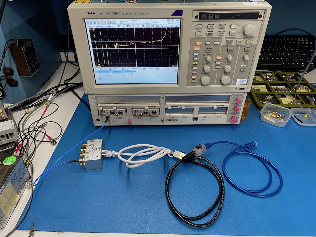
Full version: I finally got a chance to use the scope with the TDR, so I did
some basic testing of various off-the-shelf Ethernet patch cables:
* Cat7, with per-pair foil shield and an overall foil shield, ASINs
B07ZTR648R and B07ZTRR8RP
* Cat6a, with only an overall foil child, ASIN B071JYKDDN
* Cat5e, unshielded, ASIN B001V5Q9LC
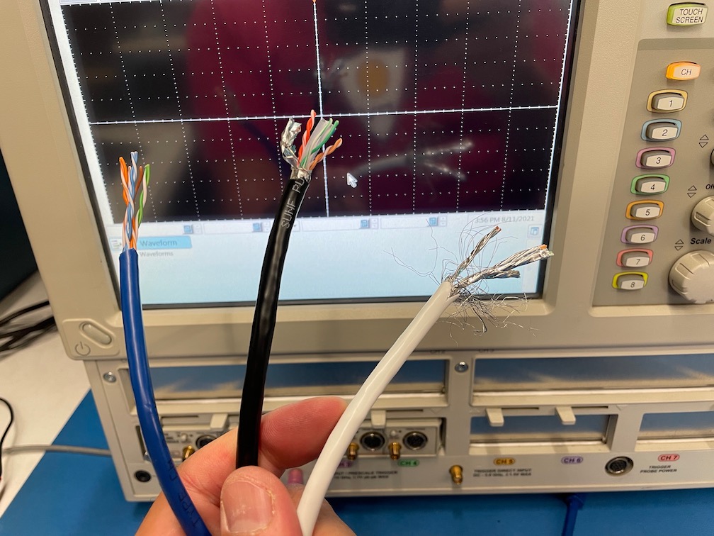
https://www.kan.org/pictures/EthernetPatchCablesShielding.jpg
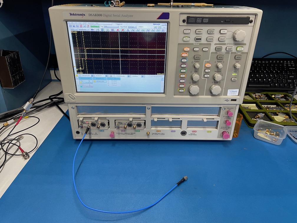
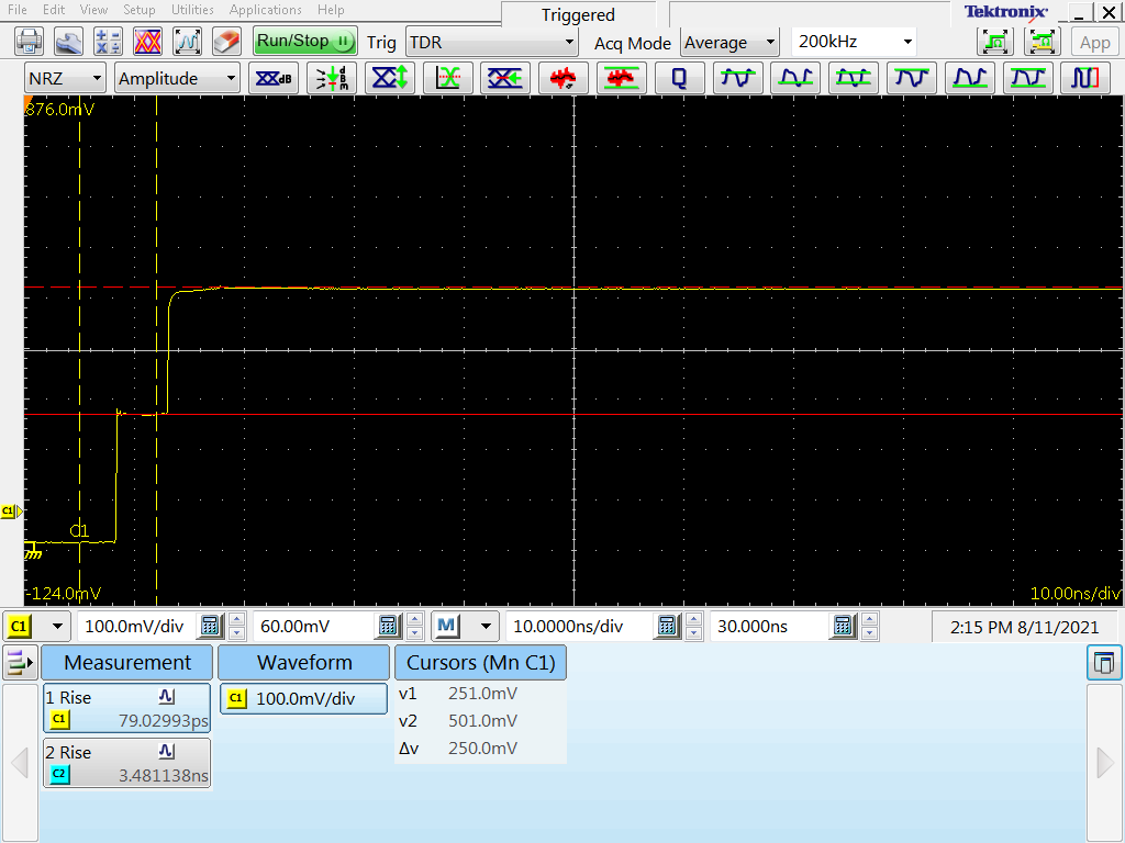
1) First I put a 3' length of 50 Ohm coax on the TDR head to establish a
baseline incident pulse height of 250 mV and a reflected open circuit height
of the expected +250 mV:
https://www.kan.org/pictures/TDR_50Ohm_Coax.jpg
https://www.kan.org/pictures/TDR_50Ohm_Coax.png
2) Next I added an SMA-RJ45 adapter and a 10' length of Cat7. The non-driven
side of the twisted pair, and the other unused circuits in the bundle, are
all tied to GND:
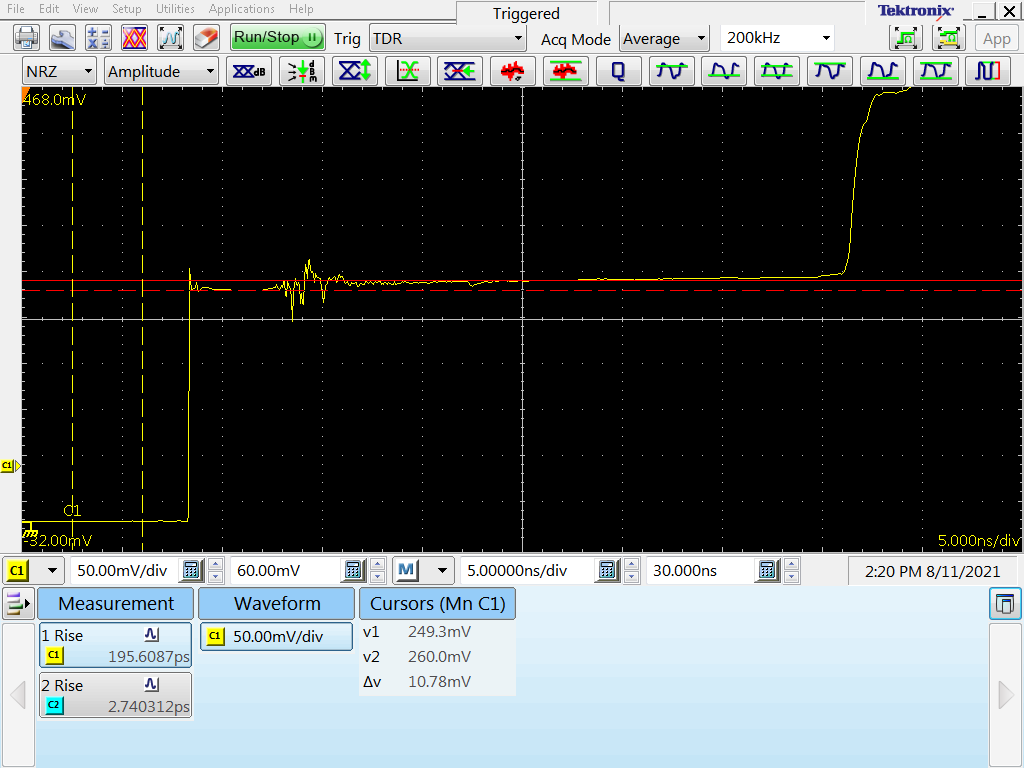
https://www.kan.org/pictures/TDR_50Ohm_Coax_RJ45_10ftCat7.jpg
https://www.kan.org/pictures/TDR_50Ohm_Coax_RJ45_10ftCat7.png
The reflected wave along the Cat7 section was about ~10 mV, so ð = 10/250=
0.04. If my math is correct, that works out to a single-ended impedance of
about (1.04/0.96) * 50 = ~54 Ohms.
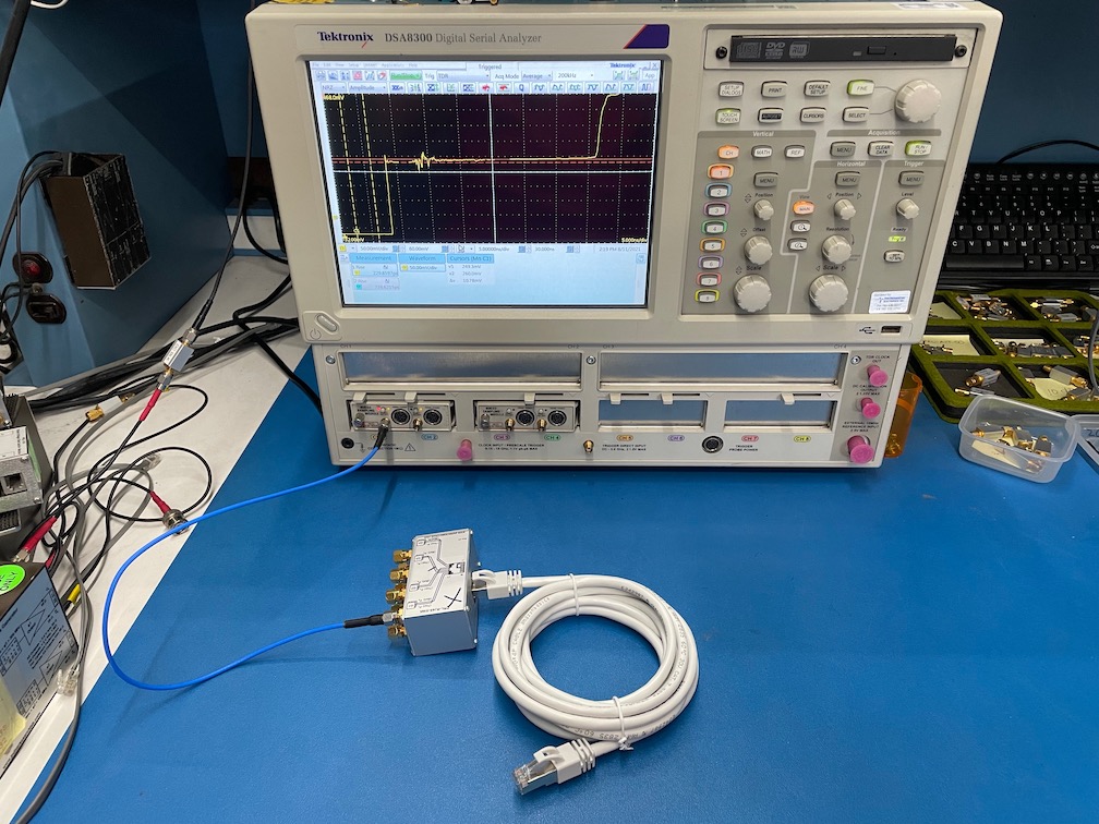
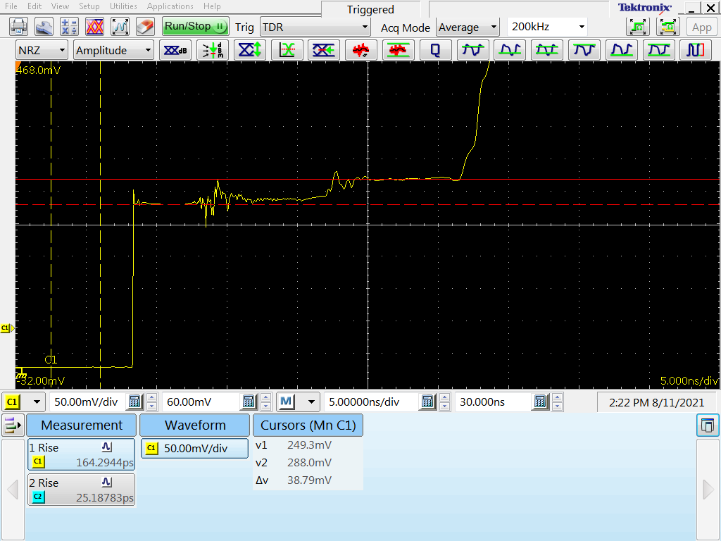
3) Then I replaced the 10' of Cat7 with 3' of Cat7, and added a shielded RJ45
coupler and 3' length of Cat6a:
https://www.kan.org/pictures/TDR_50Ohm_Coax_RJ45_3ftCat7_3ftCat6a.jpg
https://www.kan.org/pictures/TDR_50Ohm_Coax_RJ45_3ftCat7_3ftCat6a.png
The Cat6a section of reflected wave is ~39 mV, which yields an impedance of
~68 Ohms.
4) Lastly I added a 3' section of Cat5e:
https://www.kan.org/pictures/TDR_50Ohm_Coax_RJ45_3ftCat7_3ftCat6a_3ftCat5e.jpg
https://www.kan.org/pictures/TDR_50Ohm_Coax_RJ45_3ftCat7_3ftCat6a_3ftCat5e.png
The Cat5e section of reflected wave is something like ~56 mV, depending on
where you place the cursor, which yields an impedance of ~79 Ohms, but that
measurement isn't very robust, and the waveform looks terrible anyway, so I
wouldn't ever use unshielded Cat5e in an application like this.
In fact, Cat7 was approximately the same price as the Cat6a at equivalent
lengths (sometimes cheaper!), pre-made Cat7 patch cables are readily
available in lengths up to 100', and the Cat7 was not any stiffer than the
Cat6a, so there's really no reason that I can think of _not_ to use Cat7
instead of lesser cables.
As to why anyone would use "Ethernet" cables in this way, I have many
customers in test and system integration applications (e.g. board-to-board,
box-to-box, and rack-to-rack) with very high signal counts, and adapting from
SMA to RJ45 can reduce the cable count by 8x, and the cabling cost by >8x.
We make several level translator modules (e.g. TTL to LVDS or RS422 to TTL)
that use up to 8 paired SMAs for the differential side, and adapting these to
RJ45 for long runs across the lab, across the test range, or under the ocean
has worked very well. But several customers have asked if they could use the
same technique for single-ended signals, and I didn't have an answer.
Now I do, and the STPs inside Cat7 looks like an acceptable substitute for 50
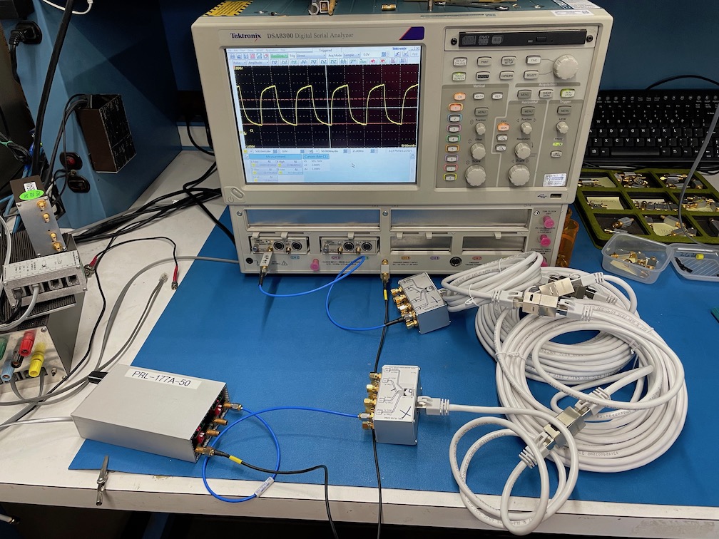
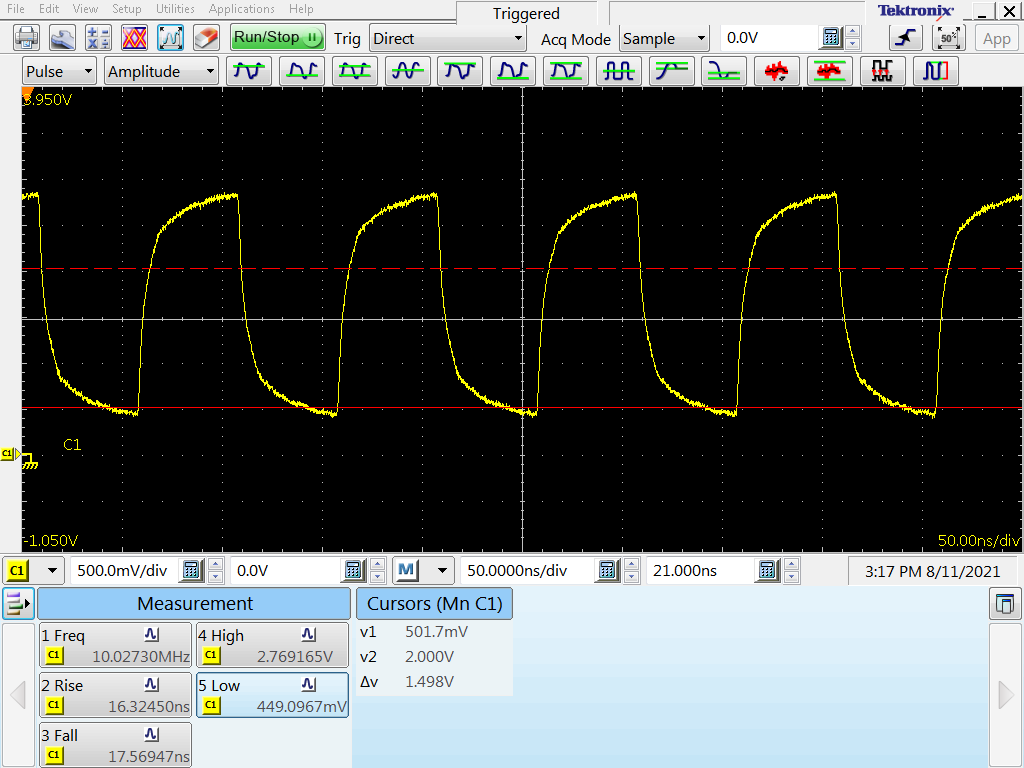
Ohm coax, when driven single-ended. I was able to carry a 10 MHz, DC-coupled,
TTL clock over 91' of Cat7 and still make valid TTL levels on the far side.
(The 91' was just all the Cat7 cables I had available, coupled together,
because I originally didn't think I was going to do any testing at that
length):
https://www.kan.org/pictures/10MHzTTL_91ft_Cat7.jpg
https://www.kan.org/pictures/10MHzTTL_91ft_Cat7.png
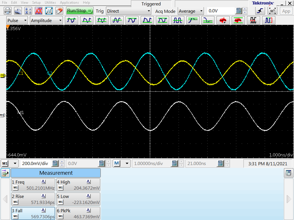
Of course AC-coupled differential signaling would be far better, as I was
able to push a 500 MHz clock over that same cable with >450 mV differential
swing at the far end:
https://www.kan.org/pictures/500MHz_DiffTTL_91ftCat7.png
but some customers don't have that option, and are stuck with single-ended
signals.
Corrections and comments welcome, especially if I've done the math wrong!
On Aug 9, 2021, at 10:37 AM, Todd Hubing <hubing@xxxxxxxxxxx> wrote:
Steven,
I can't think of any situation where one would send a single-ended signal
over an unshielded twisted-wire pair and be concerned about the
characteristic impedance. Single-ended signals drive twisted-wire pairs with
a common-mode voltage equal to half the signal voltage. At very low data
rates (e.g. <500 kbps) over limited distances, this is generally not a
concern. But at those data rates and distances, the characteristic impedance
is not a concern either.
At higher data rates, a common-mode voltage greater than about 1 mV at any
signal harmonic is very likely to cause a radiated emissions problem. In
automotive applications, even 100 microvolts can be too much.
Todd
-----Original Message-----
From: si-list-bounce@xxxxxxxxxxxxx <si-list-bounce@xxxxxxxxxxxxx> On Behalf
Of Steven Kan
Sent: Friday, August 6, 2021 5:17 PM
To: si-list@xxxxxxxxxxxxx
Subject: [SI-LIST] Single-ended impedance of Ethernet twisted pairs with
respect to GND?
Hi all,
I know that the nominal impedance of the twisted pairs in Cat5e/Cat6a/Cat7
Ethernet patch cables is 100 Ohms ± some tolerance:
https://en.wikipedia.org/wiki/Category_5_cable#Characteristics
https://en.wikipedia.org/wiki/ISO/IEC_11801#Classes_and_categories
But is the single-ended impedance of a pair specified or defined with
respect to GND, if I run a single-ended signal (e.g. TTL) over one leg of a
pair and then tie the other leg of the pair to GND on both sides of the
cable?
Will the shielding (none for 5e, outer for 6a, and per-pair+outer for 7)
affect the single-ended impedance if one half of the pair is already tied to
GND?
My preliminary empirical testing suggests that each pair is much closer to
50 Ohms than to 100 Ohms for single-ended signals, but I wanted a sanity
check from y'all.
Thanks!------------------------------------------------------------------
------------------------------------------------------------------
To unsubscribe from si-list:
si-list-request@xxxxxxxxxxxxx with 'unsubscribe' in the Subject field
or to administer your membership from a web page, go to:
//www.freelists.org/webpage/si-list
For help:
si-list-request@xxxxxxxxxxxxx with 'help' in the Subject field
List forum is accessible at:
http://tech.groups.yahoo.com/group/si-list
List archives are viewable at:
//www.freelists.org/archives/si-list
Old (prior to June 6, 2001) list archives are viewable at:
http://www.qsl.net/wb6tpu