
For breakaway connectors on my rocket, I had originally planned to use
DE-9 connectors and RJ-45 jacks w/o the tab. But I was having trouble
figuring out to keep the protuberances to a minimum and I didn't like
the the off-axis loads on the pins and shells. I remembered the MagSafe
connectors for Apple laptops but I couldn't find anything off the shelf
that was: 1) orderable, 2) had enough pins, and 3) was easy to integrate
into the skin of a rocket.
It doesn't look too complicated so I decided to try making a custom
version. I found these Mill-Max spring loaded pins:
https://www.mill-max.com/engineering_notebooks/detail/78
Connectors with 8-pin arrangements are readily available from Digikey
and Mouser:
https://www.digikey.com/products/en?keywords=419-10-208-00-006000
https://www.digikey.com/products/en?keywords=818-22-008-10-001101
You can also get the loose pins and just press fit them into a block.
These magnets were the right size:
http://www.magnet4sale.com/n42-3-8x1-8-neodymium-rare-earth-disc-magnet-with-4-countersink/
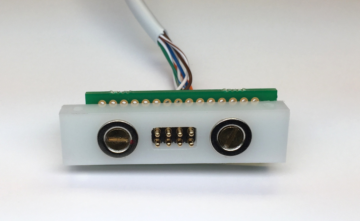
Here are some photos of a prototype I made yesterday.
http://www.watzlavick.com/robert/rocket/rocket1/photos/IMG_3630m.JPG
(removable side w/ spring pins)
http://www.watzlavick.com/robert/rocket/rocket1/photos/IMG_3633m.JPG
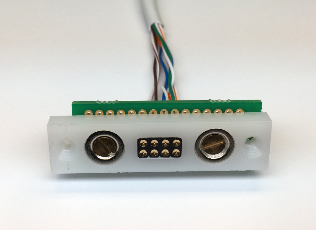
http://www.watzlavick.com/robert/rocket/rocket1/photos/IMG_3631m.JPG
(vehicle side w/ target pins)
http://www.watzlavick.com/robert/rocket/rocket1/photos/IMG_3632m.JPG
http://www.watzlavick.com/robert/rocket/rocket1/photos/IMG_3635m.JPG
(mated assembly)
The white acetal blocks are 0.5 by 2.0 inches and the pin spacing is 0.1
inches. The parts cost is just under than $15.
I went with the concave target pins instead of the flat ones for the
vehicle side because I thought they would be better for the battery
charging connections. The contacts are rated at 2A continuous, 3A
peak. The spring loaded pins have a travel of 0.055 inches with a
spring force of .15 lbf at mid-deflection so a connector with 8 of them
needs at least 1.1 lbf of compression to hold it together. The magnets
have a spec of 4.2 lbf but it's not clear if that's with another magnet
or a steel plate. I need to get a fish scale or set up a load cell for
a quick measurement.
To register the two assemblies together, I recessed the magnets by 0.02
inches on the vehicle connector and then let the magnets protrude and
equivalent amount on the removable connector. The magnets are strong
enough that if you get them anywhere close to each other, they just want
to snap in place. I used opposite polarity magnets on each end of each
connector so you can only connect the male and female portions in one
orientation. I drilled two holes in each end of the removable portion
to attach a lanyard so when the vehicle lifts off, it won't pull on the
wires. The two halves separate cleanly as expected.
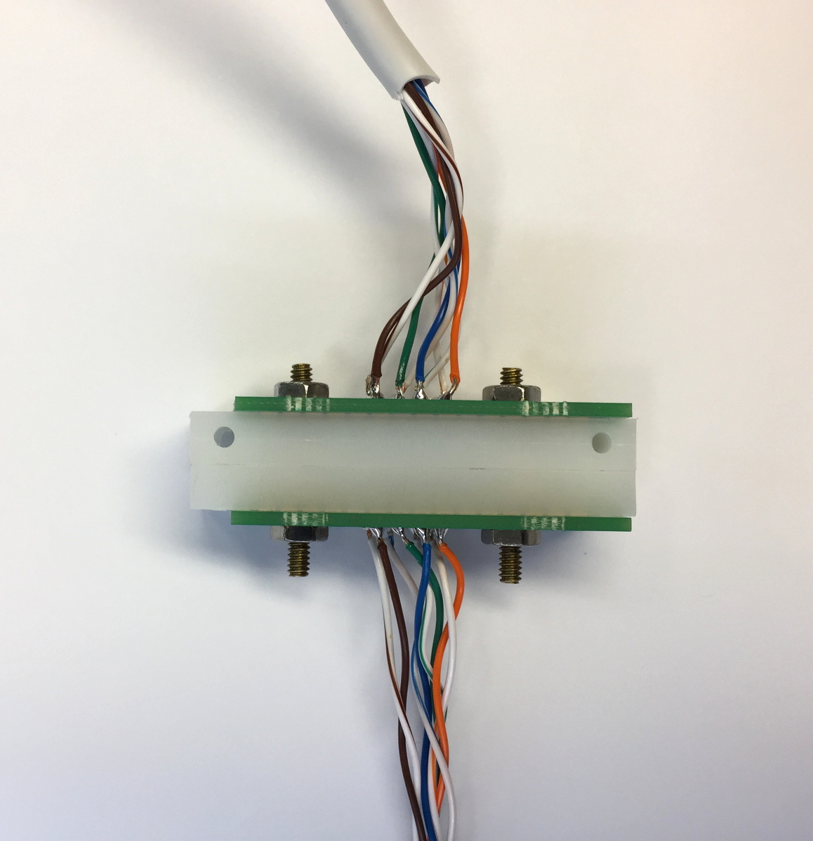
The PC boards shown are just some proto boards I had laying around - for
a real installation, I would get some small PCBs made from Oshpark that
either terminate in pads or a connector like a Molex SL or RJ-45. Or,
just use the solder cup versions of the pins.
To test the signal integrity of the connector, I cut a network cable in
two and wired it to each side. I'm only going to use it at 100Base-T
speeds (and you only need 2 pair for that) but at GB speeds, iperf shows
894 Mb/s in one direction and 938 Mb/s in the other. I didn't maintain
perfect cable twist up to the pins so maybe that's why it's not the same
in both directions. The original unmodified CAT-5E cable ran at 938
Mb/s. I don't have a fast enough oscilloscope to look at the eye pattern.
The vehicle side with the target pins is almost completely flush so once
I decide how to do the skin around the avionics bay, this concept should
work well. For the removable side, I would provide strain relief for
the cable and use some potting compound to protect the exposed connections.
-Bob