[SI-LIST] Re: small signal AC model for Current mode DC_DC converters, for full PDN simulation
- From: "Allen Mayar/EXTON/USA/SALES/KEMET/US" <allenmayar@xxxxxxxxx>
- To: "Istvan Nagy" <buenos@xxxxxxxxxxx>
- Date: Mon, 23 Mar 2009 10:48:04 -0400
Istvan:
Regarding the RLC lumped models for decoupling caps, to avoid errors in
Electrolytic capacitors (Tantalum/Aluminum and polymers of both) it is
helpful to plot a more complex model that considers the RC ladder effect
(to mimic the capacitance loss with the increased frequency). Also for low
ESL<1.2nH it is important to include a RL network to mimic decaying ESL
with increasing frequency.
You can import the Electrolytic models that takes RC ladder effect into
consideration from the site:
http://www.kemet.com/kemet/web/homepage/kechome.nsf/weben/kemsoft
Instructions:
http://www.kemet.com/kemet/web/homepage/kechome.nsf/file/KEMETSpiceman361x.pdf/$file/KEMETSpiceman361x.pdf
Kind Regards
Allen Mayar
Be gentle with your ecosystem, print only when necessary
"Istvan Nagy" <buenos@xxxxxxxxxxx>
Sent by: si-list-bounce@xxxxxxxxxxxxx
03/22/2009 06:22 PM
To
<si-list@xxxxxxxxxxxxx>
cc
Subject
[SI-LIST] small signal AC model for Current mode DC_DC converters, for
full PDN simulation
Hi
I would like to model a power distribution system in frequency domain with
a
spice-like AC analysis, with all elements of it, together.
For decoupling capacitors, I can use RLC lumped models, for IC pins
something similar, for power planes and package planes, I can use an
electromagnetic simulator to create a touchstone file that I can import
into
the program (QUCS, or Agilent ADS).
But, for the voltage regulator, I think I have to create a small signal
model to include in the simulation as a subcircuit. This model must have
the
same output impedance versus frequency response, as the original DCDC
converter has, nothing else hast to be the same (switching circuits are
not
needed in the model, nor correct voltage levels). I dont want to model the
DCDC converter with a single inductance or similar model, but put the
whole
control loop equivalent circuit into the simulation. the whole thing is
described here:
http://www.buenos.extra.hu/download/PowerIntegrityDesign_prj.rar (there is
a
pdf in it, and some circuit files) The "circuit" is all the models and
elements of the PDN together.
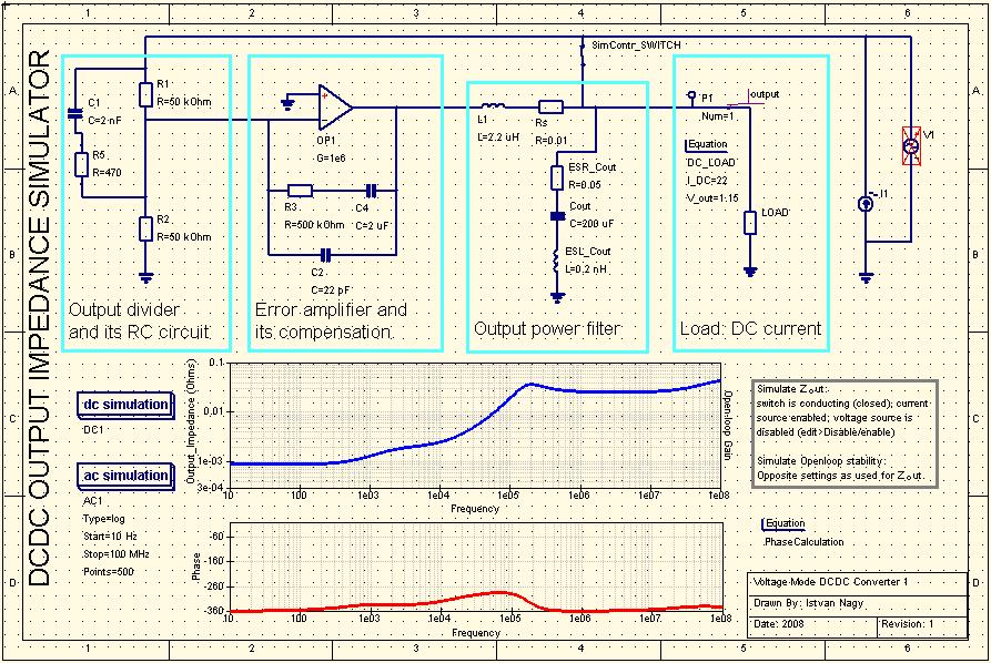
For a voltage mode converter, I think it is quiet straightforward how to
make the equivalent circuit (
http://www.buenos.extra.hu/download/voltagemode.jpg ), but for a current
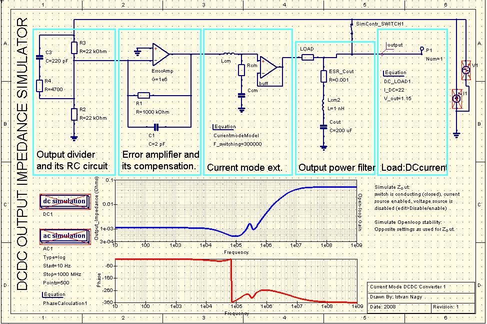
mode converter, it is trickier. My assumption was this: I read somewhere
that a current mode converter has a double pole at the half the switching
frequency, and a single pole at the 1/(2*TT*R_load*C_out). So, based on
this, I made an equivalent circuit which has the same poles and no zeroes,
so the same transfer function:
http://www.buenos.extra.hu/download/currentmode.jpg The circuit element
parameters are automatically calculated based on the provided switching
frequency, load current, some other elements are coming from the original
schematics, like the compensation RC networks... Maybe this way of
modelling
is not perfect for this purpose, but I think it's better than just using a
single inductor (or an RLC model) for representing the whole DC/DC, or
than
guessing about the transient response.
Is this model correct, or if not, how should I make it to be correct?
I am not shure in this part.
regards,
Istvan Nagy
CCT, UK
------------------------------------------------------------------
To unsubscribe from si-list:
si-list-request@xxxxxxxxxxxxx with 'unsubscribe' in the Subject field
or to administer your membership from a web page, go to:
//www.freelists.org/webpage/si-list
For help:
si-list-request@xxxxxxxxxxxxx with 'help' in the Subject field
List technical documents are available at:
http://www.si-list.net
List archives are viewable at:
//www.freelists.org/archives/si-list
or at our remote archives:
http://groups.yahoo.com/group/si-list/messages
Old (prior to June 6, 2001) list archives are viewable at:
http://www.qsl.net/wb6tpu
THIS CORRESPONDENCE CONTAINS CONFIDENTIAL INFORMATION OF KEMET ELECTRONICS
CORPORATION AND ITS AFFILIATED COMPANIES. If you have received this e-mail and
it was not intended for you, please let us know, and then delete it. We thank
you for treating our confidential information in a courteous and professional
manner.
DISCLAIMER: Although we have taken reasonable steps to reduce risks against
viruses, the reliability of this method of communication cannot be guaranteed.
It can be intercepted, corrupted, or delayed, or it may arrive incomplete,
contain viruses, or be affected by other interference. The opening of any
attachments to this e-mail indicates your agreement to hold us harmless and
release us from liability for any damage sustained as a result of this
transmission.
------------------------------------------------------------------
To unsubscribe from si-list:
si-list-request@xxxxxxxxxxxxx with 'unsubscribe' in the Subject field
or to administer your membership from a web page, go to:
//www.freelists.org/webpage/si-list
For help:
si-list-request@xxxxxxxxxxxxx with 'help' in the Subject field
List technical documents are available at:
http://www.si-list.net
List archives are viewable at:
//www.freelists.org/archives/si-list
or at our remote archives:
http://groups.yahoo.com/group/si-list/messages
Old (prior to June 6, 2001) list archives are viewable at:
http://www.qsl.net/wb6tpu
Other related posts: